Tuesday, October 24, 2006
More Tyre Pictures
 There has been some interest in the larger than normal tyres I am using, so I thought a couple more pictures were appropriate. While my whole aim is to handle poor surfaces better than the standard tyre, there is a limit as to how much I want sticking out of the bottom. In order to control this I have used a narrower spacer between the top of the tyre and the fairing. The space is of the order of 3/4", so I will have to keep an eye on the mud build up in there.
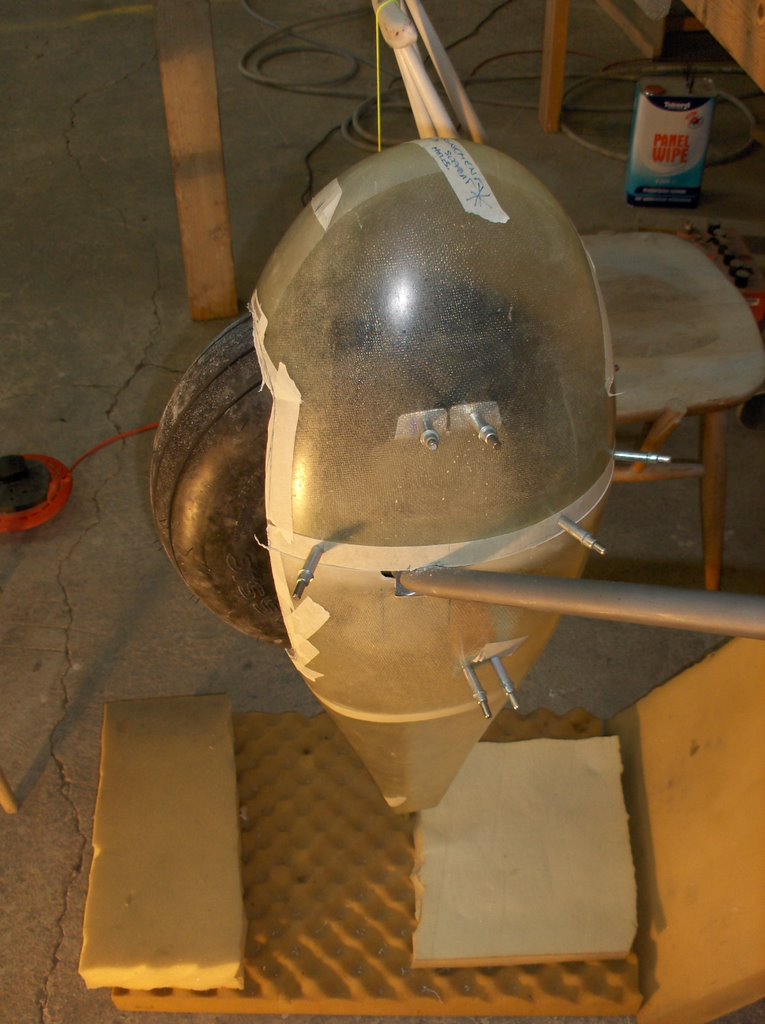
This picture shows the tyre inside the fairing. I am far from finished but the fairing is in position wrt the tyre. It shows just how much is sticking out. From memory of building my -9A it looks less once the weight of the aircraft is on the wheel.
I will run the tyres at a lowish pressure also to increase the flotation.
Wednesday, October 11, 2006
Wheel Spat.
 My unorthodox approach to getting the spat aligned is working well. For me the difficult bit was deciding where the centre points on the spat were. Aligning them with the yellow strings you can just see them in this picture, was easy, once I had that. I know they are pointing in the correct direction, unless gravity is having an off day. Statistically unlikely. I also know the engine frame is aligned to within 0.1 deg with a digital level.
The other big advantage is that I have a much better view from underneath, to see the tyre spat junction, for working out tyre clearance. [I need to make a nice job of that so the RV6,7 and 9 drivers see a nice job as I shoot by overhead! :-) ]
 This is where the day ended. The spat is on. The next job is to drill the holes between the front half of the spat and the U-810. Once these are done it will be all locked in place pretty well with clecos. Then I will cut out more clearance for the tire.
I will probably then turn to the left wheel, since I cant do much more to this one before I mix up some glass resin to build reinforcing pads inside the spats.
The shape and texture of these things makes them appear to be alive at times. They can be quite hard to hang on to. Foam rubber on the floor to cushion them each time you drop them is useful. The other learning point is don't waste your time trying to write / mark directly onto them. Stick masking tape on and write on that.
Monday, October 09, 2006
Landing Gear
 When I built my -9A, I found I spent a lot of time on the floor trying to align the wheel spats and fairings. I was never designed to work like that, and I did not find it a particularly easy task. This time I am going to try the following.
If I place the engine frame in the horizontal plane the wheel fairings need to be exactly in the vertical plane. It then seems relativly easy to define the vertical with a plumb bob, so I know how to align the wheel fairings. I have never heard of anyone doing it this way. I wonder if there are any pitfalls. I think I will ask on VANS airforce.
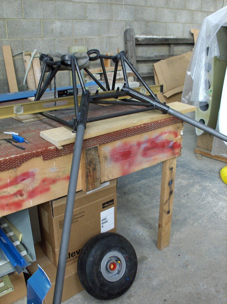
 My task is made a bit more complicated because I am using oversize tyres. These are 380x150-5. It is 15" dia and 6" wide. I am not the first to use them in the UK. Clearly I will have a little tyre more sticking out of the bottom, and will loose a couple of MPH, but the ground contact area will be much increased enabling my -4 to handle soft ground much better. Nearly everywhere I land is grass so it will be a significant advantage.
 Assembling the items on the axle seemed more complicated than the last time I did it. It ended up like this. I was pleased to have a Supercub, with Cleveland brakes, in my hanger just outside the workshop door. VANS plan leaves a little to be desired on this point. I think the second one will be easier.
At the close of play today (that is a cricket term for Colonial readers) it looked like this.
 I guess I need to tidy up! Never my strong point.
![]()